The Practical Guide to FDDI -- Physical Connections
FDDI has a sister, CDDI, which uses ordinary Cat5 twisted pair cable (the C
stands for Copper) and RJ45 connectors. The pinout isn't the same as for
Ethernet cables, but if you can make your own cables then you're set. CDDI
is effectively identical to FDDI except for using copper; everything
on the previous pages applies to CDDI as well.
FDDI Connectors
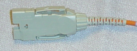
MIC connector
The MIC connector, sometimes also called the FDDI connector,
is common on concentrators and older cards. Its major problem
is that it is physically large and many card formats, such as
EISA or PCI or MCA, don't have enough space on the back panel
for two connections. One MIC connector contains two fiber
connections.
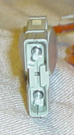
MIC connectors are keyed in two different ways. First, they're
keyed so you can't put them in upside down. Secondly, there is
an optional key indicating what port type it is. In the
concentrator photos, you can see the
color-coded key inserts on the ports if you look closely.
|
A MIC female connector from the side. Note that the
thing sticking
out of the connector is just a dust cover.
Looking down into the connector from the end,
with the dust cover removed.
|
|
SC connector
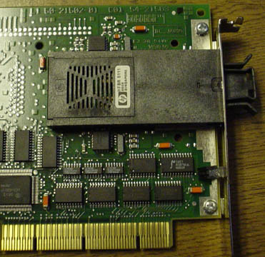
The SC connector is common on newer cards because it is smaller.
Technically, the connectors shown here are dual SC, since each
individual connector only contains one fiber, and two are
needed for an FDDI connection. Dual SC connectors are small
enough that two will fit on a PCI card back panel. It's easy to get
confused between SC and ST connectors. I remember that SC are
scware -- lame but effective. Another trick that's been
reported is "C for Click, T for Twist".
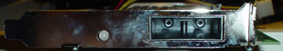
Dual SC connectors are keyed so you can't put them in upside
down. You can see the keying slots on the ports and the
matching tabs on the connector on the right.
|
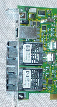
A DAS card with two dual SC connectors, from the
side.
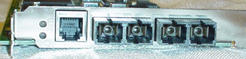
Looking down into the connectors from the end.
|
 |
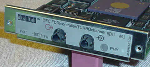
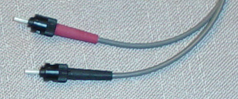
ST connector
ST connectors are uncommon. Like SC, each individual
connector only contains one fiber, and two are needed for an
FDDI connection. Unlike SC, there is no such thing as a dual ST
connector, so the male connectors are usually color-coded so
that the Rx and Tx connections (labelled on the female
connectors) can be crossed over from one end to the other (i.e.
the fiber connected to Tx at one end obviously has to be
connected to Rx at the other).
ST connectors work similarly to BNC connectors: there is a tab on
the connector which lines up with the slot on the port (visible on
top in the photo), and then
the port has two tabs (visible on the sides in the photo)
which mate with a rotating sleeve on the
connector. The sleeve twists, locking the connector onto the
port.
|
 |
 |
Note that many FDDI cards have an "optical bypass" port. It's usually a DIN
or an RJ45 connector (as in the photos of the SC card above).
Do not confuse an RJ45 optical bypass port with a
CDDI port. An optical bypass switch, which connects to the optical bypass
port, is an optomechanical relay that physically modifies the light path to
route around a failed or powered-down interface. It connects like this:
Also note that these connectors are used by things other than FDDI. ST
connectors are most common on the various flavors of 10-megabit Ethernet
which use fiber optics, such as 10baseFL. SC connectors are
used for 100baseFX Fast Ethernet over fiber and for ATM over fiber.
FDDI Cabling
FDDI normally uses multimode 62.5/125 μm (micrometer) fiber. Optical fibers
are available in both single-mode and multimode types, and rated for
different wavelengths within those types. For example, 50/125 μm is another
common multimode type. This is important, because if you get the wrong type
it will not work! Been there, done that. There are some cards
which use other cable types (for example, cards meant to drive very long
cable runs, for which single-mode fiber is better), but 99% of the time
you're going to want 62.5/125 μm multimode.
Putting connectors onto ordinary wire can be enough of a nuisance. It's
much harder to do so for fiber optics, requiring special equipment to get
perfectly polished surfaces. The best way to get FDDI cabling is to buy it
premade. You can find a lot of it on Ebay.
Another caveat with fiber optics: be careful about bending them! They break
more easily than wire.
Also, too sharp of a corner can cause a
cable to not work even without doing permanent damage. Fiber optics work by
internal reflection: the light hits the walls of the fiber at a shallow
angle and virtually all of it reflects back into the fiber. A sharp corner
may increase the angle too much, decreasing the efficiency of the
reflection and also causing the light to reflect more
times as it goes down the fiber, diminishing below the detection
threshold before it reaches the other end. That said, fiber optics aren't
that scary, either. I have some which go through a bend about three inches
in radius and they work fine.
CDDI Connectors
CDDI uses RJ45 connectors. The table below shows the pinout for each end of
the cable. I order the colors from left to right while looking at the
underside of the connector with the wire emerging downward from the
connector.
| orange-white | brown-white |
| orange | brown |
| green-white | green-white |
| blue | blue |
| blue-white | blue-white |
| green | green |
| brown-white | orange-white |
| brown | orange |
CDDI Cabling
CDDI uses ordinary Cat5 unshielded twisted pair. Except for the pinout
differences, any cable which can run Fast Ethernet will work fine for CDDI
as well.
<< BACK |
NEXT >>
All text and pictures copyright (c) 2003
James Birdsall.