With info on how to upgrade your R4000/IP17 supplied by Bert Heise
Use this info at youir own risk!
One day when I was filling the SIMM slots on our R4400/150MHz IP17 board, I noticed that the rev number of the board (030-0512-003) was a piece of paper stuck over an older rev number (030-0212-009 Rev B). Also there appeared to be some strange modifications to the circuitry via the use of some external blue wires. So when I got an R4000/100MHz IP17 board I decided to have a look at its rev number as well and try to record the visible differences between the boards. Sure enough, the rev number on the R4000 board (030-0258-003) is also on a piece of paper stuck over an older rev number (030-0212-007 Rev A).
Here are the visible differences in five parts.
Update February 2001: When I wrote this page (about about 1.5 years ago), I only had a few IP17 boards to compare. Since then others have investigated these differences and it seems that the modifications described in parts 1-4 are present on some, but not all, R4400/150 AND R4000/100 IP17s. This is good news as it seems that these modifications are probably a bug fix and that the base boards are probably the same. Consequently the sixth part of this document has a procedure for upgrading your R4000/100 IP17 to an R4400/150 IP17 by replacing the socketed running gear (ie. PROM, oscillator and CPU).
If finding the PROM from an R4400/150 IP17 is too hard then you can still get a speedup because Bert has also found that if you upgrade the CPU to a R4400/150 and use a 66MHz oscillator, then your Crimson should work just fine as a 134MHz R4400! A very rare config indeed :-)
These procedures were developed and tested by Bert Heise ([email protected]) - thanks Bert!
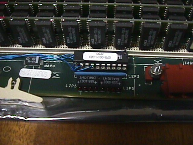
Part 1 - The 20 pin PAL just near the IP17 power connector
Power connector is just to the right, SIMM bank behind, top clip to
the left. There are four wires running from the chip with the white paper
label (which is 070-0814-003 with 7CD0 under this number). The first three
are visible in the full size image. The last one runs behind the chip to
the last leg on the right. For the purposes of this discussion, we'll number
the legs from front left in an anti-clockwise manner. Thus:
Part 2 - Where do the four wires go?

The four wires go along the top of the IP17 from the chip shown in part 1. This picture is oriented such that the backplane connectors are parallel with the bottom of the photo. Wire ? splits off from the rest just past the SIMM bank and heads down to a chip between the two banks shown. Wires ?,? and ? continue down to the chips shown in part 3.
Part 3 - Three wires go here
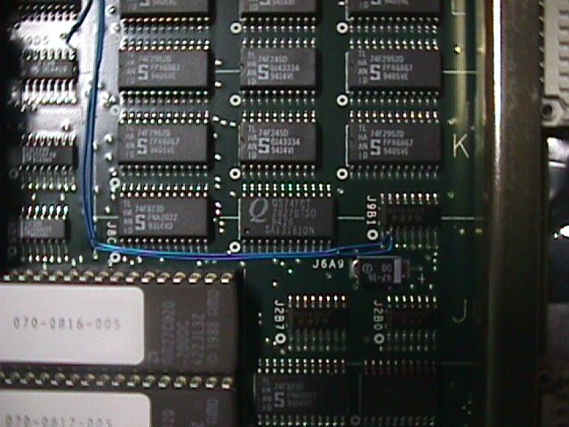
Wires ? and ? go to the same leg of the chip in the lower right of the photo. Wire ? goes to a leg of the chip shown in the upper left of the photo.
Part 4 - One wire goes here
Wire ? goes to the leg of the chip shown in the centre of the photo.
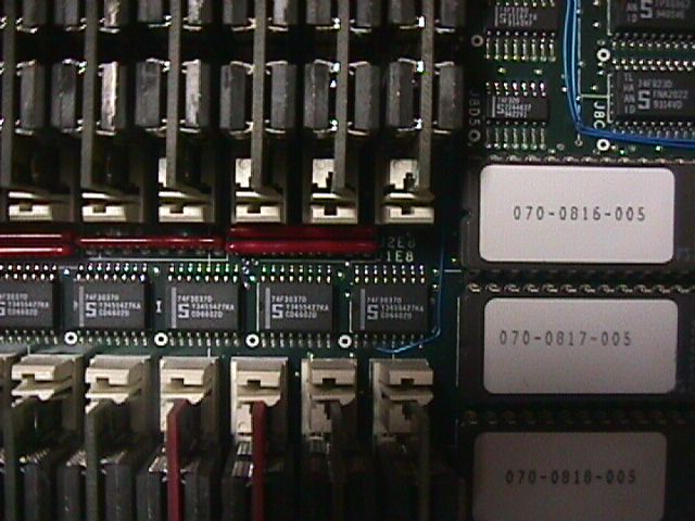
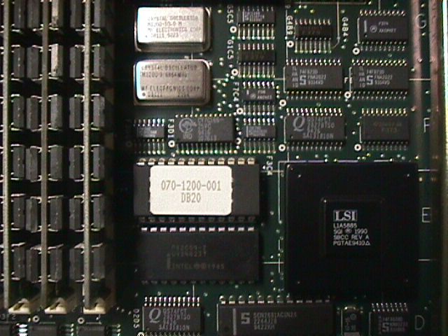
Part 5 - The PROM chips
Thats almost it. Apart from the oscillator and the CPU (obviously) only the PROM chip is different. This chip is a removeable chip and it is in a socket near location F3C4. On the R4400 board this chip is rev 070-1200-001 DB20 whilst on the R4000 board this chip is rev 070-0815-002 DA20.
Here's a picture of the chip and its surrounds just in case the location number doesnt get you there. To orient youself, this picture is taken such that the backplane connectors are parallel to the right hand side of the image with the lower rear SIMM slot visible at the left.
Part 6 - How to upgrade your
R4000/100 IP17
1 - Upgrading to an R4400/150 IP17
According to other info (most noteably Bert Heise ([email protected])), the modifications to my 030-0512-xxx R4400/150 IP17 described in parts 1-4 above are NOT present on all 030-0512-xxx R4400/150 IP17 boards! Indeed some other Crimson owners have reported that their R4000/100 IP17 boards have the same modifications as my R4400/150 IP17 board. Seems as though these modifications are a bug fix for some boards and ARE NOT necessary to run an IP17 at 75/150MHz. Bert has confirmed this by upgrading his R4000/IP17 to a 75MHz (well 80MHz actually) R4400/150 IP17.
What you need to do the upgrade:
To do the upgrade you can follow this procedure:
If you can't get the 070-1200-xxx DBxx 150MHz IP17 PROM, then Bert Heise has found that you can still get a good speedup by using a 66MHz oscillator with your existing 070-0815-xxx DAxx R4000/100MHz PROM and an R4400/150 CPU.
What you need to do the upgrade:
Bert reports that the machine boots correctly with hinv reporting a
134MHz IP17 processor!